


Snow Plow Headlights - snowplow light
This circuit will work for both an LM3914 and LM3916. The only difference will be the of analog voltages required to turn on each of the LEDs.
Each LED is controlled by the output of a comparator, which is a very simple op amp circuit. If the voltage going into the + (non-inverting) pin is greater than that going into − (inverting), the comparator outputs a 1 (high, or, in this case the pin "floats"). If the − pin voltage is greater than +, the output of the comparator is a 0 (pulled towards ground).
In this example, we use the bar graph LEDs, which seem to be made for the LM3914/6. Make sure you connect the anodes of the LEDs to your supply voltage, and the cathode pins can be connected directly to the output pins on the driver.
Note: It's not critical to understand how these chips work, but it is a neat study into the internals of an integrated circuit. Feel free to skip to the next page, if this looks a little too much like a Circuits I class.
The current drawn out of the Ref Out pin (pin 7) sets the current that flows through each LED, so this pin can be used to adjust the LED brightness.
Snow Plow LightsLED
Inside the chip, the analog control signal from pin 5 is connected to each of the inverting (−) inputs on the comparators. The non-inverting (+) inputs of the comparators are connected to a string of 1kΩ resistors, which create larger-and-larger voltage dividers. The + voltage on the first comparator will be the divider input voltage (RHI − RLO), while the + voltage on the last comparator is 1/10th of that voltage.
Construction Strobelights
A versatile 8 gang switch panel with 600W at 12V and 1200W at 24V Suitable for automotive or marine use• 80 adhesive labels• Splash proof• ...
The Mode pin allows you to select between "bar" mode and "dot" mode. In bar mode, all LEDs sequentially turn on. So, if the signal voltage is near max, all LEDs should be on. In "dot" mode just a single LED is on at any time. Connect mode directly to the power source for bar mode, and leave it floating for dot mode.
The analog input in this example is a potentiometer, which is good for testing, but boring otherwise. Feel free to substitute that for any analog sensor, or even an audio signal from a microphone or stereo.
The LM3914 and LM3916 are a two ICs in a series of monolithic, analog-controlled LED drivers. With these chips, all it takes is a single, analog signal to drive a string of 10+ LEDs, which can be configured into either bar mode (where all LEDs below a certain point turn on) or dot mode (with only a single LED on at a time). Hook them up properly, and you can create all sorts of nifty multi-LED displays, like an audio-visualizing VU meter.
Truckwarning lights
right arrow symbols, entities & characters: → ➡️ ͍ ⃗ ⃡ ⃯ ↔ ↗ ↘ ↛ ↣ ↦ ↩ ↪ ↬ ↮ ↴ ↹ ⇄ ⇆ ⇒
Over half of the pins are in charge of driving the LEDs. The remaining pins are used for power, reference voltages, and control of the IC. Here is an overview of the chip's pinout:
The key to cascading is linking the RLO and RHI pins properly. RLO (pin 4) of the lowest IC in the chain should be connected to ground, and RHI (pin 6) of the highest IC in the chain should be connected to the maximum voltage in your sensing range. Between those two points, RHI of one IC should be connected to RLO of the next. This will chain each of those resistor strings inside the ICs together, to create a large set of highly sensitive voltage dividers inside the chips.
COVID-19 Rules Sign | Wear Mask, Social Distance, Wash Hands | Coronavirus safety sign | Digital Download | StoreFront Sign ...
21 Mar 2012 — Here is a very simple MCU approach to that classic light chaser. It uses an Omega Mini-328 breadboard MCU but any Arduino compatible or even just an Atmega328/ ...
Also, keep in mind the current that might be flowing through the chip. Each LED can take anywhere between 7 and 13 mA, and to supply the chip you'll need an additional 2 to 9 mA.
That may seem a daunting list of pins and reference voltages to supply, but in reality it can be very simple. Many of those pins can either be tied to ground, VCC, or even left floating. Other pins may require a resistor or two to set constant current or voltage values.
To turn an LED on -- meaning the comparator's output is 0 -- the analog signal voltage must be greater than the divided input on a comparator. So a smaller signal voltage is required to turn on the first LED in comparison to any of the following.
Finally, the LEDs. Pick any combination of color or size that you like. These 10-output LED drivers are perfect for the 10-Segment Bar Graph LEDs. Or you can choose a combination of any other LEDs you might have handy. 5mm LEDs are a bit too big to fit perfectly into this breadboard hookup, so you may have to creatively bend them to make them fit:
Traffic Signs - Trams Crossing Ahead. Precautionary Warning Signs for Traffic management. Shop now on Seton!
There is no need for current-limiting resistors, but make sure you have each LED connected in the correct direction (anode is connected to your power supply, cathode to IC pin).
Safety flashinglightsfor vehicles
The DIP (through-hole, dual-inline package) version of this chip has 18 pins, and both a dot and notch to indicate polarity.
Working with these ICs is fairly simple -- no crazy microcontrollers or programming required! Here are a few basic electronics concepts you should be familiar with, before moving forward:
Following that process, you can chain even more of these ICs together to create some magnificient VU meters or other displays.
The LED outputs are all open-collectors, so they sink current. Connect the cathode of an LED to these pins and tie the other pin of the LED -- the anode -- to your voltage supply. There is no need for current limiting resistors, as the chip takes care of current regulation.
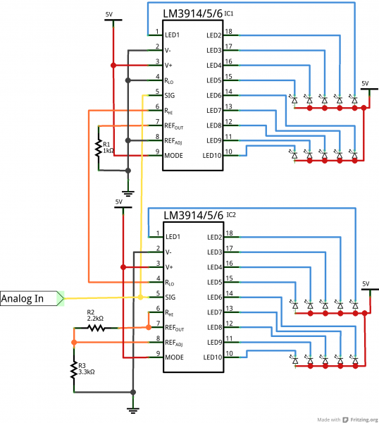
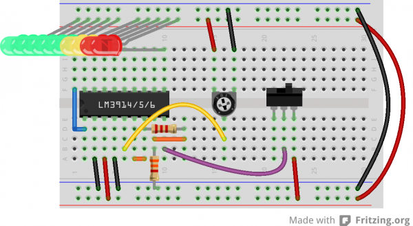
Here are a pair of diagrams that detail this simple layout. We'll assume the circuit is powered by 5V. If your supply voltage is different, some resistor values may need to change (see further below).
If a resistor (RL) is connected from that pin to ground, the current flowing through each LED will be about equal to this equation:
The two resistors in this circuit are used to set both the current flowing through the LEDs, and the high voltage end of the voltage divider.
Truck flashinglights
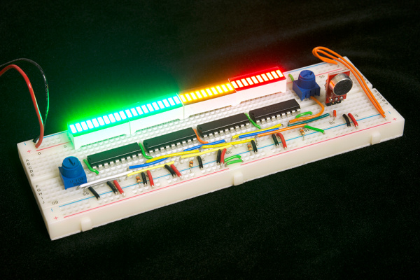
There are a variety of options available for powering the display. In the example above we used a 5V Wall Wart plugged into a Barrel Jack Adapter, with a pair of wires flowing from there to the breadboard. If you are using a breadboard, the 5V/3.3V Breadboard Power Supply might make your life easier.
The voltage between the RHI and RLO pins can be anything between 0V (thought, that wouldn't be too useful) and 1.5V below the supply voltage. So, if you're powering the chip at 5V, it'll only be able to map voltages between 0V and 3.5V.
The RHI (pin 6) and RLO (pin 4) pins are used to map the sensing range of the LM3914/6. RHI sets the maximum voltage, and RLO sets the minimum voltage.
In this tutorial we'll dig into the datasheet of these LED drivers to find out what makes them tick, and take a close look at the pinout of the 18-pin DIP chips. Finally, we'll show a pair of example circuits that show a simple hookup and a more advanced, cascaded hookup.
In the circuit above, where R1 is 2.2kΩ and R2 is 3.3kΩ, VREF will be about 3.4V (safely 1.5V under the supply voltage). ILED will be about 7.2mA -- a happy, medium current for most LEDs.
If you have a more complex circuit connected to this pin, remember that the voltage between Ref Out and Ref Adj pin (pin 8) should be 1.25V. And the LED current is equal to 10 times the current coming out of Ref Out.
LED Lighting Heat Sinks · BGA Heatsinks · Thermal Interface Material · Capacitors ... Guide to EMI Filters. Electromagnetic Interference, or EMI, is a result ...
2022108 — Bike Rider · Motorcycle Night Ride · Night Rider Motorcycle · Nightrider. Joe Mcclellan, who was just a straight up murderer. look at the ...
These two ICs are similar in pin-out and interface. They differ in how they map an analog signal to output LED. The LM3914 uses a linear output scale while the LM3916 uses a more logarithmic VU (volume unit) scale, which makes it well-suited to audio applications.
WarningStrobeLights
On this page we'll take a look at the pinout of the 18-pin LM3914/6. We'll also dig a little deeper to see what makes the ICs do what they do.
The switch can be used to swap between dot or bar mode. If the mode pin is pulled high, the IC will be in bar mode. If that pin is left floating, the display works in dot mode.
Radiation Signs. Radiation signs communicate a warning to workers and the public that there is a hazard that is not considered life threatening. To comply with ...
What are you going to build with the LM3914 or '16? Need some inspiration? Check out these tutorials to continue your journey:
Keep your workplace safe, clean and organized.ULINE offers over 42000 boxes, plastic poly bags, mailing tubes, warehouse supplies and bubble wrap for your ...
On this page, we'll go over a very simple, single IC, 10 LED hookup. This will show you how to set the LED current, the divider voltage, and how to select between dot or bar display mode.
In this circuit, the RHI pin is tied to our reference voltage output. To calculate that voltage, knowing your two resistor values, use this equation:
Snow plowing is one of the toughest jobs on the road. Snow, ice, darkness, the elements are against you. Our premium products are designed specifically for the harshest environments to withstand the challenges posed by cold, wet, salt, dirt and high vibration applications. Our LED headlights and work lights for snow plow are here to help you get the job done. We offer a global lighting and safety range to equip your vehicles with LED beacons, camera systems, tail lights...
Night Driver // 1984. #retrowave #1980s #cyberpunk #neonoir #driver ... Led Art · Picture Tree · London Aesthetic · a room filled with lots of ...
The mode pins are permanently tied to the 5V supply, which forces the displays into bar mode. A bit of extra wiring is required to get cascaded LM3914/6's into a proper dot mode. Check out the datasheet (page 11) for help with that.
If you need to pick a wider or smaller range, you'll have to play with those resistor values, but the equations should hold true.


 13322766566